Technical article
Whitepaper EncoderBlue goes reflective

With the continuously increasing adoption of auto-mated machinery in various applications, positioning devices are becoming an essential part of many systems. For precise motor control, encoders are becoming the most popular solution.
An encoder can operate on different principles, such as: optical, magnetic, mechanical, etc., providing incremental or absolute position data. An encoder may also provide multi-turn information when needed and all these possibilities result in a flexible product, offered in different sizes and suitable for all kinds of environments. Owing to this highly flexible nature of an encoder, together with the increasing use of automated machines, more and more applications are beginning to take advantage of position encoders.
In order to better suit different applications and their specific requirements, new encoder technologies are constantly being developed and implemented. The reflective optical encoder with blue light is one example of such a new technology, and is being released by iC-Haus as the iC-PR and iC-PX Series integrated circuits.
This article details the features and advantages of this new approach.
Table of Contents
1、 Fundamentals of optical encoders and new challenges
2、 Comparing transmissive and reflective optical encoders
3、 Reflective solutions
4、 IC-PR features and assembly tolerances
5、 IC-PX features and assembly tolerances
6、 Advantages
7、 Applications
8、 Summary
9、 References
Fundamentals of optical encoders and new challenges
Ranging from industrial production lines to household appliances, automation is taking part in the design of most new products. In this context, linear and rotary encoders are the ultimate solution for accurate motor positioning, replacing aging components such as potentiometers, synchros, resolvers, etc.
An encoder can operate on different principles, such as optical, magnetic, mechanical, and others. De-pending on the sensor type, an encoder provides incremental or absolute position data. The first one outputs only information about changes in position, usually in the form of AB quadrature pulses. These are interpreted as forward or backward steps by a counter processor. Incremental encoders typically use a once-per-revolution index signal to reference the start or reset of the counting position. Absolute encoders, on the other hand, deliver the complete position value, which is available at any time (the absolute position is known without requiring to pass through an index mark). Absolute encoders can also provide multi-turn information when needed, which gives the number of complete rotations of the encod-er.
All these different operating modes result in a variety of products, offered in different sizes and suitable for all kinds of environments. With this highly flexible nature of the encoder, together with the increasing use of automated machines, more and more applica-tions are beginning to take advantage of the function-ality of position encoders for motion control.
When comparing the different principles behind an encoder, optical encoders are regarded as the most precise ones. Each approach has its own benefits, with optical encoders usually providing the highest resolution and accuracy. However, optical encoders also come with their own disadvantages. Due to its optical nature, the sensor components are sensitive to dust, oil, and other obstacles that may interfere with the optical path. This is usually solved by a tightly sealed enclosure for the encoder. Another difficulty faced by high accuracy optical encoders is the influence of position errors, meaning that assem-bly tolerances are generally very small. This leads to a higher complexity in the manufacturing process of the encoder, requiring high accuracy assembly techniques to achieve proper signals. This problem alone impedes many companies from manufacturing encoders, since their manufacturing process cannot achieve the required level of precision.
Another difficulty faced by some applications regard-ing optical encoders is the space required by the encoder. An optical encoder must have a protective case, and the internal structure required by traditional (transmissive) optical encoders result in a considera-ble height (Z dimension). This is due to the fact that the light source (LED), code disc and optical sensor must be optically aligned with a suitable distance between them. This requires an encoder height that prevents it from being adopted in some compact applications, such as miniaturized robotics.
Even consumer products are entering the realm of fine positioning control with the introduction of household vacuuming robots, flying drones, and house automation (auto-adjustment of curtains, ventilation, etc.). The manufacturing of these products is executed on a large scale, and assembly variations must be accepted in order to have a high production efficiency. Additionally, the compact sizes of some of these products also prevent the adoption of large-dimension encoders, which are usually acceptable for industrial machines.
The first solution to these requirements would be the use of magnetic encoders. Simple on-axis magnetic encoders can be easily manufactured and require very little space, thus representing a logical choice. However, as the resolution and accuracy require-ments of these applications also evolve, the magnetic encoders are faced with a technical limitation. Currently, on-axis magnetic encoders cannot reach very high resolutions and neither do they provide the highest accuracy unless more advanced techniques are used (for example: using external interpolators to increase the resolution of the system), which unfortu-nately results in higher costs. Additionally, magnetic encoders require more robust shielding against magnetic interference, which in some working environments can be very challenging.
These new demands driven by the market have inspired the industry to search for ways to adapt the characteristics of the optical encoder, making it implementable under these new conditions.
Comparing transmissive and reflective optical encoders
Traditional optical encoders rely on transmissive optics, which is a mature and well-known technology for encoders. However, it also has its own inherent drawbacks, limiting its application in certain scenari-os. An alternative technology for encoders is based on reflective optics, which tries to improve on the features where transmissive encoders tend to fall short.
Although transmissive and reflective encoders use the same basic principle – an optical sensor that receives light modulated by the movement of a coded disc – their physical structures differ considerably. The figure below represents the basic structure of a traditional transmissive encoder:
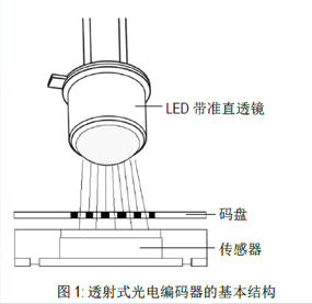
Figure 1: Basic structure of transmissive optical encoders
As illustrated in Figure 1, the transmissive solution works fundamentally by using the code disc to create obstructions to the light path at some places while letting the light through at other places. The main requirement of the code disc is a precise division into transparent and non-transparent areas. This is usually achieved by a lithographic process, where a coating material (such as chrome) is deposited on top of a transparent substrate (such as glass). The quality of the disc is defined by the accuracy of the litho-graphic process, as well as the contrast between transparent and non-transparent areas.
The advantage in this technique is that the lithograph-ic process is mature and can achieve very high accuracy, allowing a very fine code marking on the disc. This results in better signal quality for high resolution encoders.
On the other hand, this structure also brings disad-vantages: in order to achieve good results, the illumination has to be as homogeneous as possible. This requires a parallel light beam that is achieved only by adding collimation lenses to the system. This optical structure considerably increases the axial length of the encoder, which is undesirable for many applications.
Another disadvantage is that the accuracy with which the sensor must be positioned relative to the code disc is directly related to the density of the marking on the disc. If very precise lithography is used, the position of the sensor relative to the code disc must also be very precise, otherwise the quality of the signals will suffer considerably. This includes the XY displacement of the sensor, as well as the air gap between the sensor and the code disc (Z distance). If the marking on the code disc is very narrow, the light diffraction after going through the disc will have a bigger impact on the signal, therefore a very tight air gap between sensor and disc is required in order to receive good signals. For high-end encoders, assem-bly accuracy requirements are under 0.1 mm, which unfortunately is unfeasible for many manufacturers. Even for manufacturers that achieve such accuracy requirements for the end product, the assembly still requires a careful positioning calibration, usually conducted individually for each encoder using optical or electrical inspection and followed by a fine correc-tion of the generated signals. This process is very time consuming, limiting the efficiency of the manu-facturing process.
The problems mentioned above can be tackled by using reflective optical encoders. The figure below depicts the structure of this kind of solution:
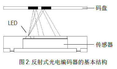
Figure 2: Basic structure of reflective optical encoders
The most evident difference seen in Figure 2 com-pared to the transmissive solution, is the absence of the light source with collimation lenses opposite the sensor. A reflective encoder works by emitting light from the same side as the sensor (relative to the code disc), and selectively reflecting portions of the light to the sensor. In this case, the fundamental characteris-tic of the disc is the division between reflective and non-reflective areas (in contrast to the transpar-ent/non-transparent nature of the transmissive discs). As with the transmissive discs, the quality of the signals depends on the disc marking process (lithog-raphy) and the contrast between the divided areas (in this case, reflective/non-reflective).
Reduced physical dimensions is a noticeably clear advantage of this solution. Without collimation optics, and with the LED light source on the same side as the sensor, the total volume of the encoder can be reduced substantially. This factor alone already enables the encoder to fit a wider range of applica-tions, compared to the transmissive solution. Com-pact optical encoders are possible, sharing many of the advantages of traditional optical encoders.
The reflective encoder solution can have different variations. A typical example is the addition of plastic lenses on top of the sensor and LED to shape the light beam to have the desired properties. However, an even better solution is achieved using a lens-free design. Eliminating the external lenses completely can be accomplished and results in more flexibility and robustness: lenses need to be specifically designed for different applications, they limit consid-erably the operating distance range between the LED/Sensor and the disc, and at the same time add restrictions to the operating conditions, such as the allowed temperature range. Even without additional lenses, very high resolutions can be achieved by carefully controlling the light source spot size. With standard LED illumination, it is already possible to achieve medium-high resolutions with this approach.
In this case, we see the most advantageous scenario: as long as the resolution is kept in a reasonable range, we have an optical encoder with very small dimensions, no external optics requirement, good resolution and accuracy (which can be easily en-hanced further with interpolation techniques), and very low assembly requirements.
We can compare main characteristics of transmissive and reflective encoders:
Transmissive Optical Encoder:
Mature technique
High resolution and high accuracy
Significant height (Z dimension)
Difficult assembly: small tolerances, mechanical stability during operation
Small code disc to sensor air gap
Good resolution and accuracy:
Easy assembly
Large mechanical tolerances
Flat design: decreased height
Large code disc to sensor air gap
Reflective solutions
The reflective optical encoder principle has been known for some time. However, difficulties in achiev-ing good results in a convenient and easy to use integrated chip have limited its implementation to a few product lines from a small number of manufactur-ers.
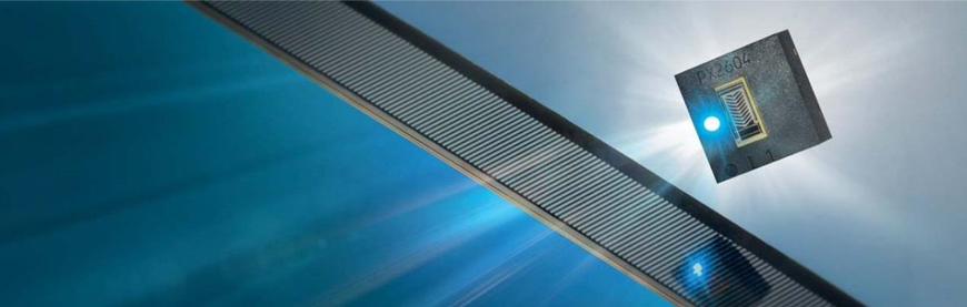
The recent introduction of the EncoderBlue® products (optical encoders with blue LED as light source) has proven useful also for the reflective encoder segment.
The EncoderBlue® technology provides many ad-vantages, such as:
higher efficiency (same optical power with less operating current),
higher signal sharpness and contrast,
less output signal jitter.
The EncoderBlue® technology is already in use with transmissive optical encoders (such as the iC-PT H-Series and iC-PNH Series), but these properties can also considerably improve the signals in reflective encoders. Therefore, iC-Haus combined the ad-vantages of EncoderBlue® technology and the reflective encoder approach, releasing the all-new incremental optical encoder iC-PR Series and iC-PX Series.
IC-PR features and assembly tolerances
The first product carrying the reflective EncoderBlue® technique is the iC-PR Series. This is a lensless reflective optical design for an incremental encoder.
ABZ digital quadrature outputs with up to 16-fold interpolation is possible. This interpolation is realized on-chip through pin configuration. There is the optional functionality of providing the analog signals at the output. The analog sine/cosine signals can be connected to an external interpolator for enhanced interpolation.
As expected from an EncoderBlue® solution, the iC-PR encoder also integrates a blue LED to be used as the illumination source. This blue LED comes with all the previously mentioned advantages, and is driven by a closed-loop control circuit, which automatically adapts the LED current according to the amplitude of the signals generated by the sensor. This ensures a stable operation of the encoder, compensating variations such as LED efficiency deviations due to temperature or aging effects, or even mechanical variations such as the air gap between the chip and the code disc.
The iC-PR Series is composed of different variants, each with HD Phased Array photosensors optimized for a specific code disc diameter and resolution. All the selectable functions are configured by pin, thus do not require time-consuming programming proce-dures.
The main features of the iC-PR Series are listed below:
ABZ quadrature output with index
No optical lense
Optimized for reflective code discs of Ø 4, Ø 14, Ø 26 and Ø 43 mm
Monolithic design: integrated HD Phased Array, signal conditioning, S/D conversion and LED power control
Integrated blue LED with auto power control: EncoderBlue®
The main features of the iC-PX Series are listed below:
AB quadrature output
No optical lens
Optimized for reflective code discs of Ø 26 and Ø32 mm
Monolithic design: integrated HD Phased Array,
signal conditioning,
S/D conversion and LED power control
Integrated blue LED with auto power control:EncoderBlue®
Digital output (pin selectable 1x to 16x interpolation)
Operating temperature: – 40 °C to + 105 °C
optoDFN package 3 x 3 x 0.9 mm
Low power consumption: typ. 13 mA (incl. LED)
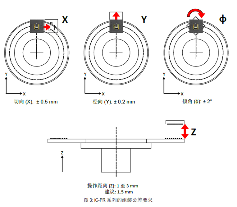
Due to the absence of an index mark, the mounting of
the sensor relative to the code disc is even more
flexible. Figure 4 shows the typical assembly variation
tolerances for the iC-PX Series.
Advantages
Standard package: This all-integrated solution is
assembled in an optoQFN for the iC-PR (QFN dimensions with a glass window for the opto sensor) and optoDFN for the iC-PX, which eases the PCB design considerably. The footprint as well as the chip height is the same as other QFN/DFN standard ICs. This eliminates the hassle of creating design-specific PCB footprints, required by other reflective products in the market.
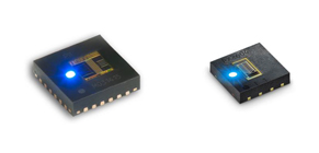
Figure 5: Standard QFN/DFN footprint and dimensions for iC-PR and iC-PX
High-temp and overall height: These reflective encoder ICs do not hinge on any lens or secondary optics and therefore reduces the overall height of the encoder housing. A plastic lens would not only increases the height of the system, but also limits the maximum operating temperature, usually to + 85 °C. With such lensless reflective technology, the maxi-mum operating temperature is + 105 °C, as often required by the industry.
Wider air gap: Another limitation of a reflective solution with a lens is the air gap range. Due to the focal length of the lens, the gap tolerable range is narrow, usually ± 0.25 mm. This reflective technique unites a lensless design with an automatic LED power control, which together increase the permissi-ble air gap range to 1 to 3 mm, always with stable outputs.
Higher quality signals: These reflective solutions also integrate a blue LED and HD Phased Array photodi-odes, optimized for different disc sizes. The blue LED together with the blue-enhanced HD Phased Array photodiodes generate sharper signals with higher contrast. This results in reduced output jitter, even after interpolation. The photodiodes are optimized for different code disc dimensions covering a wide range of diameters, even an ultra-compact 4 mm diameter disc. This optimization is especially important when using the analog outputs for external interpolation, as the quality of sine/cosine signals remains outstand-ing, allowing high-accuracy and high-resolution interpolation
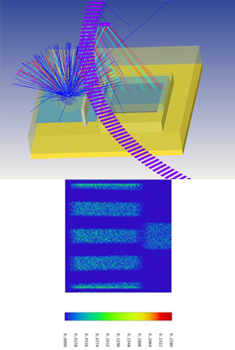
Figure 6: Basic optical design and ray tracing model of a reflective encoder sensor
Easy to use: The iC-PR and iC-PX Series are com-pletely pin configurable, avoiding the complexity of programming and calibration, and thus reducing the encoder manufacturing time. Together with the relaxed assembly tolerances, the overall efficiency of the encoder production line can be increased consid-erably.

Applications
The reflective encoders can be used in different applications, sometimes as a replacement for other types of encoders and in some cases in new applica-tions not yet served by current encoder technology.
Most motion control devices with incremental posi-tioning detection can benefit of the iC-PR or iC-PX Series, but the main focus of the reflective encoders is on compact encoder applications, such as:
Miniature motors and actuators
Industrial automation robots
Consumer robots
Incremental encoders
Single or multi-axis stages
Summary
The level of automation is rapidly increasing in all areas, ranging from industry machinery to household appliances. This is creating new requirements for encoders, an essential device for motion control. In this context, reflective optical encoders represent a new technology that unites high performance and compact size.
In particular, the reflective optical encoders by iC-Haus with EncoderBlue® technology offer not only small dimensions, but also robustness and superior assembly tolerances, all while providing excellent output signals.
The iC-PR and iC-PX Series are easy to use and suitable for all kinds of incremental encoders without bringing complexity to the manufacturing process. This allows a broader range of products for precise motion control.
References
[1] Wikipedia: Rotary Encoder, https://en.wikipedia.org/wiki/Rotary_encoder
[2] Absolute Encoder Design: Magnetic or Optical?, Whitepaper iC-Haus, http://www.ichaus.de/wp6_magnetic_vs_optical
[3] iC-PR Series – Reflective Opto Encoders, Datasheet iC-Haus GmbH www.ichaus.de/PR_Series_datasheet_en
[4] Basics of Rotary Encoders: Overview and New Technologies, http://machinedesign.com/sensors/basics-rotary-encoders-overview-and-new-technologies-0
[5] Basler S. (2016) Encoder und Motor-Feedback-Systeme, Springer Vieweg
About iC-Haus
iC-Haus GmbH is a leading, independent German manufacturer of standard iCs (ASSP) and customized ASiC semiconductor solutions with worldwide repre-sentation. For more than 30 years the company has been active in the design, production, and sales of application-specific iCs for industrial, automotive, and medical applications.
The iC-Haus cell libraries in CMOS, bipolar, and BCD technologies are specifically suited to realize the design of sensor, laser/opto, and actuator ASiCs, amongst others. The iCs are assembled in standard plastic packages or using the iC-Haus chip-on-board technology to manufacture complete microsystems, multichip modules, and optoBGA/QFN in conjunction with sensors.
Further information is available at www.ichaus.com